How to Draw Moment Diagrams
Moment diagrams are similar to shear diagrams, use them to find the location and value of the maximum positive and negative moment, or the moment at any specific location.
The easiest and fastest way to construct a moment-diagram is by using the areas of the regions in the shear-diagram. Before doing this you must solve for all the reactions, and solve the shear diagram.
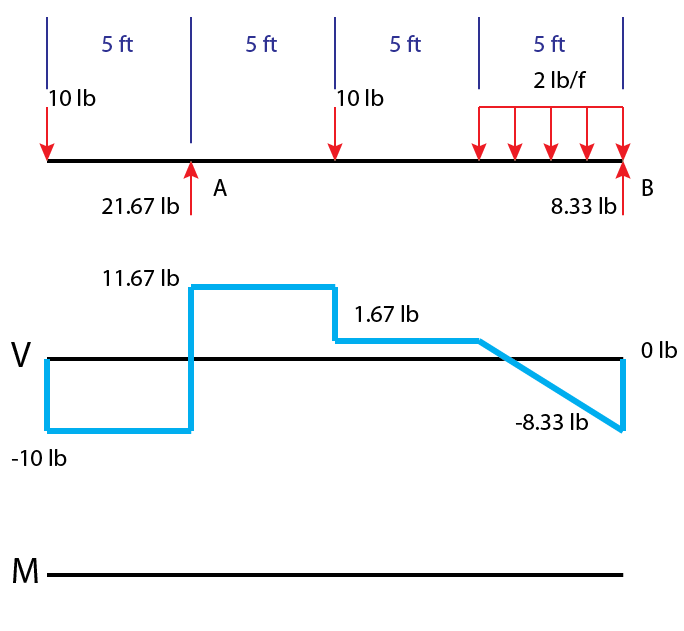
Here is a member that is solved to the desired state to begin working on the moment diagram. The start of a moment diagram (M) is below the existing shear diagram (V).
Moment diagrams, like shear diagrams, begin and end at zero. The moment in each section is the integral of that section in the shear diagram. The area regions of the shear diagram are labeled below and will be referenced further on.
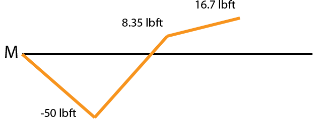
The area of the first region in the shear diagram is $$-10lb(5ft) = -50lb*ft$$. Draw a straight line from zero to -50ft*lb underneath the support at A. Draw a dot at the end point of your line so that you have the goal in sight for each segment (this seriously reduces mistakes and is faster).
The line is straight is because the shear in this segment is constant.
The area of region 2 of the shear graph is \(11.67lb * 5ft = 58.35ft*lb\). The ending point on the moment diagram for this section will be \(-50ftlb + 58.35 ftlb = 8.35 ft*lb\). Put a dot at the end point (8.35 lbft) and draw a straight line to it ( this shear segment is also constant).
The area for region 3 is 8.35 lb*ft and the shear is constant resulting in a linear moment. The moment at the end of this segment is 16.35 ft*lb.
Region 4 is different from the others, it’s a triangle instead of a rectangle. To find the area we have to find where the sloped line crosses the axis. This is done with a simple line equation:
$$ y = -2x + 1.67 $$
$$ (0) = -2x + 1.67 $$
$$ x = 0.835 ft$$
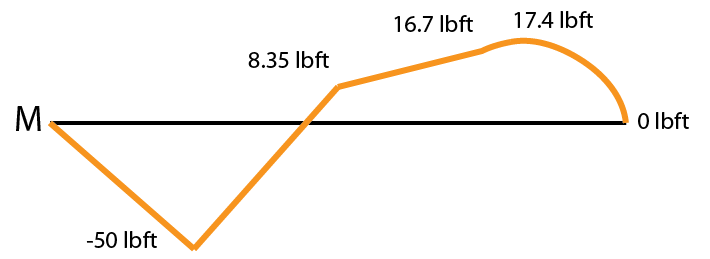
The area of the triangular region 4 is \( 0.835 * 1.67 * \frac{1}{2} \approx 0.7 lb*ft\), bringing the graph to 17.4 lbft. This region is linear so our moment graph will be parabolic.
A parabolic section has two options, it can bend upward or downward. The easiest way to tell which way it will bend is to inspect the shear diagram segment. The tall side of the triangle of region 4 is on the left side so the steepest part of the parabola will be on the left side. This parabolic section will bend upward/outward.
Region 5 is also a triangle. We know the distance of the horizontal to be \(5ft – 0.835ft = 4.17 ft\). The area is \( 4.17 * 8.33 * \frac{1}{2} \approx 17.4 \). The shear here is negative so the overall moment change will be negative and it brings you back to zero.
The tallest side of the triangle in region 5 is on the right side so the steepest part of the parabola will also be on the right side. This parabolic section will also bend upward.
This last section is clearer about the steep section of the parabola. Look how steep it is at the end of the graph near 0 versus how shallow it is at the top of the segment near 17.4. Again this is due to the tall side of the triangular section being on the far right.
That completes the moment diagram for this example. The maximum negative moment is -50 ft*lb at support A and the maximum positive moment is ~17.4 ft*lb to the left of support B.
For structural problems it is common to use the opposite sign convention so that the graph of the final moment diagram resembles the flexure of the member. I may want to explore and illustrate that later.
Posted in Structural Breadth and tagged bending moment, bending stress, mechanics, moment, moment diagram, morning breadth, pe exam, structural. Bookmark the permalink. Leave a Comment.


Leave a Comment
Comments (0)